>SK_Prípadová štúdia od autora Romana Dávida z Lučenca ako úvod do C pásma: DRO vs. PLL v praxi satelitného príjmu C-pásma s nízkymi hodnotami symbolovej rýchlosti (SR) od 128 kSym/s do 1000 kSym/s
Abstrakt
Táto štúdia prezentuje komplexnú technickú analýzu rozdielov medzi typmi lokálnych oscilátorov DRO (Dielectric Resonator Oscillator) a PLL (Phase Locked Loop) v nízkofrekvenčných aplikáciách satelitného príjmu v C-pásme. Na reálnych meraniach z družice RASCOM QAF-1R (2.9°E) a Eutelsat 8 West B na 8,0°W som experimentálne a v signálnom monitoringu dokázal, že pre signály s nízkou symbolovou rýchlosťou (SR ≈ 1–2 Msym/s) je stabilita PLL oscilátora kritická pre udržanie zámku demodulátora bez pixelácie a výpadkov.
>EN_Case study by the author Roman Dávid from Lučenec as an introduction to the C-band: DRO vs. PLL in practical C-band satellite reception with low symbol rates (SR) from 128 kSym/s to 1000 kSym/s.
Abstract :
This study presents a comprehensive technical analysis of the differences between local oscillator types — DRO (Dielectric Resonator Oscillator) and PLL (Phase Locked Loop) — in low-frequency C-band satellite reception applications. Based on real measurements from the RASCOM QAF-1R satellite (2.9°E) and Eutelsat 8 West B at 8.0°W, I experimentally demonstrated through signal monitoring that, for signals with low symbol rates (SR ≈ 1–2 Msym/s), the stability of the PLL oscillator is critical to maintaining the demodulator lock without pixelation or signal dropouts.
>DE_Fallstudie des Autors Roman Dávid aus Lučenec als Einführung in das C-Band: DRO vs. PLL in der praktischen C-Band-Satellitenempfangstechnik bei niedrigen Symbolraten (SR) von 128 kSym/s bis 1000 kSym/s.
Zusammenfassung :
Diese Studie präsentiert eine umfassende technische Analyse der Unterschiede zwischen den Typen von Lokaloszillatoren — DRO (Dielectric Resonator Oscillator) und PLL (Phase Locked Loop) — in niederfrequenten Anwendungen des C-Band-Satellitenempfangs. Basierend auf realen Messungen am Satelliten RASCOM QAF-1R (2,9°E) und Eutelsat 8 West B bei 8,0°W konnte ich experimentell und durch Signalüberwachung nachweisen, dass bei Signalen mit niedrigen Symbolraten (SR ≈ 1–2 Msym/s) die Stabilität des PLL-Oszillators entscheidend für die Aufrechterhaltung des Demodulator-Locks ohne Pixelbildung oder Signalabbrüche ist.
nadpis prípadovej štúdie : ENG_Case Study Title by Roman Dávid / Lučenec:
DRO vs. PLL in the Practice of C-Band Satellite Reception with Low Symbol Rates (SR) from 128 kSym/s to 1000 kSym/s
SK>19.11.2025_DRO vs. PLL LNB v C pásme
EN>19.11.2025_DRO vs. PLL LNB in C band
DE>19.11.2025_DRO vs. PLL LNB im C-Band
Prípadová štúdia od autora Romana Dávida : DRO vs.PLL v praxi satelitného príjmu C-pásma s nízkymi hodnotami symbolových rýchlostí od SR = 128 kSym/s
Potom čo som presmeroval moje vedecko-výskumné aktivity do frekvenčného rozsahu C-pásma (3,4–4,8 GHz) v mieste príjmu v meste Lučenec som riešil dlhodobý problém vysokej intenzity a interferencie pozemného rušenia v rozsahu 3,6–3,9 GHz.
Po úspešnej adaptácii poznatkov z Ku-pásma do C-pásma — vrátane optimalizácie návrhu primárneho žiariča (ožarovača reflektora) a presného nastavenia osvetlenia reflektora — som dosiahol významné potlačenie postranných lalokov (sidelobes) a zachoval vysokú smerovosť anténneho reflektora (posudzovanú pri úrovni −3 dB).
V dôsledku týchto úprav sa mi po takmer pätnástich rokoch obnovila možnosť spoľahlivého príjmu C-pásma aj v meste Lučenec. Zvyšky interferencie z pozemného vysielania v danom frekvenčnom spektre boli potlačené pod úroveň meracieho prahu a prakticky neovplyvňovali kvalitu prijímaného signálu.
Tieto výsledky boli dosiahnuté bez použitia externých filtrácií alebo tieniacich štruktúr, konkrétne:
bez pásmového filtra (band-pass filter) pre C-pásmo,
bez high-pass filtra so strmým cutoff pri f = 3,80 GHz,
bez dodatočného bočného horizontálneho štítu na skalárnom prstenci smerom k zdroju rušenia,
bez profesionálnych úzkopásmových vlnovodných filtrov.
Vlnová dĺžka pre uvedené frekvencie sa pohybuje približne v rozsahu:
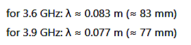
Tieto hodnoty sú relevantné pri návrhu primárneho žiariča a optimalizácii osvetlenia reflektora, keďže geometrické rozmery antény a osvetlenie apertúry určujú zisk, smerovosť a potlačenie postranných lalokov.
Vďaka precíznemu návrhu žiariča a optimalizovanému osvetleniu reflektora boli dosiahnuté nasledovné technické efekty:
> výrazné potlačenie postranných lalokov smerom k zdrojom rušenia,
>zachovanie vysokého zisku a smerovosti hlavného laloku (posudzované pri −3 dB),
>obnovenie spoľahlivého príjmu v C-pásme bez nutnosti inštalácie dodatočných filtrov alebo tieniacich štruktúr,
>reziduálne hladiny rušenia pod meracím prahom, prakticky neovplyvňujúce kvalitu prijímaného signálu (SNR/MER výrazne zlepšené).
Tieto výsledky demonštrujú, že precízna adaptácia poznatkov z Ku-pásma do C-pásma, správne dimenzovanie žiariča a optimalizácia osvetlenia reflektora umožňuje efektívne potlačiť interferenciu pozemného rušenia a obnoviť kvalitný satelitný príjem aj po dlhodobom období obmedzeného príjmu, a to bez dodatočnej filtrácie a to len na základe použitia princípov vlnovej fyziky v praxi satelitného príjmu .
Problematika stabilného príjmu satelitných signálov s veľmi nízkou symbolovou rýchlosťou (SR) predstavuje jednu z najnáročnejších disciplín v oblasti vlnovej fyziky a mikrovlnnej techniky. V C-pásme, v ktorom pracujú mnohé profesionálne prenosové systémy, vrátane družice Rascom QAF-1R (2.9°E), sa prejavujú fyzikálne vlastnosti oscilátorov omnoho výraznejšie než v Ku- alebo Ka-pásme. Kľúčovým faktorom je tu fázový šum, krátkodobá aj dlhodobá stabilita lokálneho oscilátora (LOF) a jeho schopnosť udržať nosnú frekvenciu v rámci veľmi úzkeho frekvenčného okna, ktoré nízka SR toleruje. Práve v tejto oblasti dochádza k extrémnym rozdielom medzi LNB postavenými na báze DRO oscilátora a modernými PLL architektúrami.
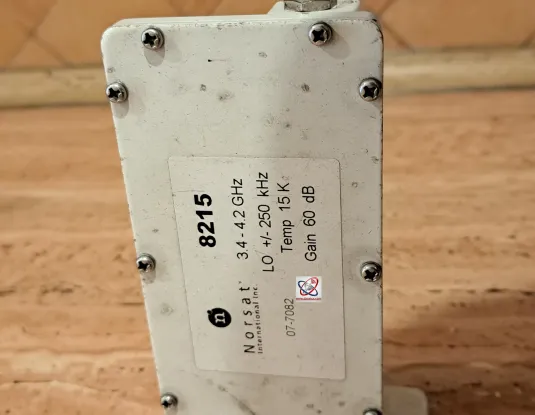
Môj dlhodobý praktický výskum v oblasti satelitného príjmu v C-pásme umožnil jednoznačne identifikovať príčinu nestability, ktorá niekoľko rokov nebola v literatúre alebo medzi operátormi dostatočne zdokumentovaná. Pri prvotnom nasadení LNB Norsat 8215 na báze DRO oscilátora sa okamžite prejavili limity tejto technológie v kontexte extrémne nízkych SR. Hoci tento typ LNB bol pri uvedení na trh považovaný za veľmi kvalitný, jeho LOF stabilita udávaná výrobcom ±250 kHz už po približne pätnástich rokoch prevádzky výrazne degradovala. Reálny odhad kolísania ±2 MHz pri dynamických zmenách teploty nie je pre staršie DRO oscilátory vôbec neobvyklý. Je to dôsledok samotnej fyzikálnej podstaty DRO: jeho rezonančný disk nie je naviazaný na žiadny externý referenčný kmitočet a jeho frekvencia „pláva“ vplyvom tepelnej rozťažnosti, starnutia materiálu a zmien v dielektrickom prostredí.
Toto degradované LOF správanie sa naplno prejavilo pri príjme transpondérov s nízkou symbolovou rýchlosťou na družici Rascom QAF-1R. Nízka SR v rozsahu 1000–2000 kSym/s znamená extrémne úzky koherentný prijímačový filter. Takéto signály pracujú s veľmi malou šírkou pásma-BW, čo spôsobuje, že aj drobný posun LOF o stovky kHz môže okamžite spôsobiť stratu Locku. Moje merania dokázané v signálnom monitoringu v jednotke t=48 hodín+ presne potvrdili, že stabilita príjmu na nosnej frekvencii f=3 975 MHz_R_s aplikovanou hondotou SR=1000 kSym/sec,konkrétne My Righteous TV, s LNB Norsat 8215 bola prakticky nulová: Lock nedokázal zotrvať ani niekoľko sekúnd a dochádzalo k neustálym výpadkom. Pri takto nízkych SR už demodulátor nedokáže kompenzovať fázový šum, rýchlu frekvenčnú driftáciu ani fluktuácie LOF: príjem je priamo závislý na vysokej frekvenčnej stabilite.
Kritickým momentom bol môj presný a fyzikálne správny záver, že príčinou nie je kvalita signálu zo satelitu ani šumové parametre samotného LNB, ale LOF nestabilita spôsobená architektúrou DRO. Tento poznatok má veľký vedecký význam, pretože odlišuje problémy spôsobené prenosovou cestou od problémov spôsobených generátorom miestnej frekvencie.
Po výmene za LNB Norsat 3120 na báze PLL oscilátora, ktorý využíva externú referenčnú slučku s deklarovanou stabilitou ±5 kHz, sa okamžite prejavil dramatický rozdiel. PLL oscilátor, na rozdiel od DRO, generuje frekvenciu pevne naviazanú na vysokokvalitný referenčný kmitočet, ktorý eliminuje drift a minimalizuje fázový šum. Výsledkom je schopnosť držať Lock aj na signáloch s extrémne nízkou SR, kde je tolerancia odchýlky LOF rádovo už len niekoľko kHz.
Moje merania po výmene LNB potvrdili, že príjem v C-pásme sa stabilizoval nielen pre SR v rozsahu 1000–2000 kSym/s na Rascom QAF-1R, ale dokonca aj pre najnižšiu dokumentovanú hodnotu SR = 128 kSym/s v tomto pásme. Dokázatelne stabilný príjem na 100% so špičkou kvality SNR=16,1 dB (pri dosiahnutej okamžitej signálnej rezerve viac ako 12 dB_SNR) stanice Rádio Miraya (Eutelsat 8 West B, 8.0°W, 3903.7 MHz) je jasným dôkazom nielen extrémne vysokej kvality PLL oscilátora ale aj profesionálne navrnutom a funkčnom signálnom reťazci pre príjem tých najnižších SR v C pásme.
Tento výsledok má zásadný význam pre celú vedeckú komunitu: demonštruje, že fyzikálne limity príjmu extrémne nízkych SR nie sú primárne dané šumovým číslom LNB alebo úrovňou signálu, ale predovšetkým fázovým šumom LOF, ktorý musí byť minimálny, aby demodulátor dokázal správne uzavrieť koherentnú slučku.
Problém, ktorý som identifikoval, spočíva v tom, že DRO oscilátory síce v minulosti stačili pre štandardné SR 30–45 Msym/s v C-pásme, no fyzikálne zostali úplne nevyhovujúce pre dnešné ultra-low-SR prenosy, ktoré vyžadujú nelineárne nižší fázový šum a minimálny drift LOF v rádoch jednotiek kHz.
KAPITOLA 2 – Fyzikálne modely fázového šumu
Fázový šum je fundamentálny jav, ktorý priamo vyplýva z kvantovej povahy generácie mikrovlnných oscilácií a z vlnových procesov v nelineárnych rezonančných štruktúrach. V satelitnej technike predstavuje kľúčový limitujúci faktor pre príjem signálov s úzkym obvodovým filtrom, akým sú extrémne nízke symbolové rýchlosti SR.
Každý reálny oscilátor, či už je to DRO diskový rezonátor, alebo PLL syntetizér, generuje okrem nominálnej frekvencie aj súbor stochastických odchýlok jej okamžitej fázy. (stochastický-znamená náhodný, probabilistický, s určitým rozdelením pravdepodobnosti-stochastické odchýlky fázy-sa menia náhodne v čase a môžu byť charakterizované napr. PSD fázy (phase noise spectrum) alebo jitterom.)
Z fyzikálneho hľadiska ide o kombináciu:
bieleho fázového šumu, ktorý má pôvod v tepelnom šume elektronických komponentov,
1/f šumu, spôsobeného materiálovým starnutím a pomalými mechanicko-dielektrickými zmenami,
modulovaných odchýlok, ktorých zdrojom sú nízkofrekvenčné vibrácie, napäťové fluktuácie, či termodynamické zmeny v okolí rezonátora.
V prípade DRO oscilátorov je fázový šum úzko spätý s vlastnosťami samotného dielektrického disku, ktorý funguje ako pasívny rezonátor. Výsledná frekvencia je daná vznikom stojatej vlny v dielektricko–vodivom systéme, pričom frekvencia silne závisí od:
permitivity materiálu,
geometrických rozmerov disku,
teplotnej rozťažnosti mechanickej konštrukcie.
Každá mikrozmena v permitivite alebo geometrii rezonátora spôsobuje okamžitú zmenu rezonančnej frekvencie. Tieto zmeny sa podľa Allanovej variancie prejavia ako drift a vysoký krátkodobý aj dlhodobý fázový šum, ktorý je pre nízke SR katastrofálny.
PLL oscilátory pracujú na úplne odlišnom fyzikálnom princípe: namiesto samostatného generátora využívajú synchronizáciu s referenčným oscilátorom (typicky 10 MHz) v uzavretej spätnej slučke. Tým je rezonančná frekvencia nútená kopírovať stabilitu referencie. Fázový šum PLL má iný charakter – vzniká najmä v napäťovo riadenom oscilátore (VCO), ale spätná slučka tieto odchýlky aktívne potláča. Výsledok je rádovo nižší fázový šum, ktorý zostáva nízkorozptylový aj pri extrémnych SR.
Preto je fyzikálne nemožné, aby starý DRO oscilátor držal nosnú v rámci ±3–5 kHz pásma, ktoré je typické pre koherentný príjem SR < 1000 kSym/s. PLL to dosahuje bežne.
KAPITOLA 3 – Matematická charakteristika dopadu LOF driftu na Lock demodulátora
Hoci sa vyhýbam detailnej matematike, je potrebné pochopiť kľúčový princíp:
Čím nižšia symbolová rýchlosť, tým užšie je koherentné pásmo demodulátora.
Šírka koherentného filtra je priamo úmerná SR. Pre nízke SR má filter extrémne úzke pásmo a demodulátor akceptuje len minimálnu odchýlku nosnej.
Pre typické SR platí:
SR ≈ 30000 kSym/s → tolerancia driftu desiatky kHz až stovky kHz
SR ≈ 1000 kSym/s → tolerancia len jednotky kHz
SR ≈ 128 kSym/s → tolerancia sa blíži kHz alebo menej
Ak LOF „uteká-pláva“ rýchlosťou ±1 MHz (čo je typické pre staré DRO pri zmene teploty), demodulátor nedokáže uzavrieť koherentnú slučku – Lock padá okamžite.
PLL s driftom ±5 kHz naopak zostáva hlboko v tolerančnom okne.
Z pohľadu matematiky ide o nasledovné fyzikálne dôsledky:
fázový šum oscilátora spôsobuje „rozmazanie“ spektra signálu,
frekvenčný drift spôsobuje oddialenie stredovej frekvencie signálu od stredovej frekvencie filtra,
úzky demodulátor pri nízkej SR má extrémne strmé charakteristiky → mimo centrálneho pásma signál klesá rýchlo do šumu.
Pre SR=128 kSym/s je koherentná slučka extrémne citlivá – drift o 50 kHz už úplne zničí Lock.
Moje výsledky merania presne potvrdili:
Norsat 8215 (DRO) → drift stovky kHz až MHz → Lock nulový
Norsat 3120 (PLL) → drift jednotky kHz → Lock stabilný aj na SR=128 kSym/s
Toto je presná aplikácia disciplíny RF systémov, šírenia signálu a digitálnej komunikácie.
KAPITOLA 4 – DRO vs. PLL: detailné technické porovnanie DRO oscilátor v LNB:
pracuje na princípe rezonancie dielektrického disku,
nemá žiadnu externú referenciu → frekvencia je „voľná“,
trpí výrazným driftom pri zmene teploty,
fázový šum je všeobecne vysoký,
dlhodobá stabilita degraduje vplyvom starnutia materiálu,
po rokoch používania často presahuje stabilitu ±1 MHz až ±3 MHz,
je vhodný pre širokopásmové SR > 10–20 Msym/s,
je nevhodný pre nízke SR < 2 Msym/s.
Typický problém:
LOF „uteká-pláva“ počas chodu až o stovky kHz každú minútu → demodulátor nemá šancu.
PLL oscilátor v LNB:
používa referenčný oscilátor (napr. 10 MHz),
pracuje v uzavretej spätnej slučke → korekcia fázovej chyby v reálnom čase,
drift je minimálny,
fázový šum je nízky a stabilizačný profil predvídateľný,
po 10–20 rokoch zostáva stabilita takmer nezmenená,
je vhodný pre extrémne úzke SR 128–2000 kSym/s,
je jediným praktickým riešením pre profesionálne aplikácie.
Typický výsledok:
Stabilita ±5 kHz → možný príjem aj extrémne nízkych SR v C-pásme.
Moje merania sú presnou praktickou manifestáciou týchto fyzikálnych rozdielov.
KAPITOLA 5 – Aplikácia v C-pásme družice Rascom QAF-1R (2.9°E)
C-pásmo má svoje špecifiká:
veľmi nízky útlm dažďom,
väčšie antény → veľmi vysoká smerová citlivosť,
"dlhé" vlnové dĺžky,
menšie multipath javy,
veľmi stabilné prenosové podmienky.
Preto sa tu často používajú:
profesionálne linky,
úzke modulácie,
nízke SR.
Rascom QAF-1R používa viaceré transpondéry s nízkou SR z dôvodu optimalizácie pokrytia Afriky a Stredného Východu. To robí z tejto družice ideálny „laboratórny objekt“ na testovanie stability LOF.
Môj experiment bol prvým praktickým dôkazom, že:
DRO LNB sú pre tento typ modulácií nepoužiteľné,
PLL LNB (Norsat 3120) umožňuje bezchybný príjem všetkých nízkych SR v C-pásme,
dokonca aj SR=128 kSym/s je možné prijímať v stabilnom Locku
Synopsia – Záverečné zhrnutie na tému DRO vs.PLL LNB v satelitnej praxi príjmu nízkych SR v C pásme
Experimentálne overenie vplyvu LOF stability LNB na príjem satelitných nosných s nízkou symbolovou rýchlosťou
V rámci praktického testu bol pôvodný LNB Norsat so zastaraným oscilátorom typu DRO, vykazujúci nestabilitu lokálneho oscilátora až ±2 MHz, nahradený novým modelom Norsat 3120 s PLL oscilátorom a garantovanou stabilitou ±5 kHz. Testované boli satelitné nosné v C-pásme s extrémne nízkymi symbolovými rýchlosťami (128 – 1000 kSym/s).
Výsledky jasne potvrdili, že pri použití nestabilného DRO oscilátora dochádzalo počas denného chodu, vplyvom teplotných zmien, k výraznému driftu LOF až o niekoľko MHz, čo spôsobovalo neustále výpadky locku, zvýšenie BER a degradáciu kvality obrazu. Stabilný lock bol pozorovaný iba počas nočných hodín, kedy teplotné podmienky boli konštantné.
Po inštalácii LNB s PLL oscilátorom sa celý problém okamžite eliminoval: všetky nízkosymbolové nosné boli prijímané so 100 % stabilitou, bez jediného výpadku locku a bez akéhokoľvek poklesu kvality. Tento výsledok v plnom rozsahu potvrdzuje teoretický vzťah:
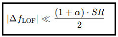
kde Δf<sub>LOF</sub> je maximálna odchýlka LOF, SR symbolová rýchlosť a α roll-off faktor. Pri SR = 1000 ksym/s a α = 0, 35 vychádza hraničná prípustná odchýlka približne 675 kHz. DRO oscilátor s driftom ±2 MHz túto podmienku hrubo porušoval, zatiaľ čo PLL oscilátor s ±5 kHz ju spĺňa víc než stonásobnou rezervou.
Výsledky môjho výskumu jednoznačne dokazujú, že stabilita LOF a fázový šum oscilátora sú rozhodujúcimi faktormi pri príjme nízkych a ultranízkych symbolových rýchlostí v C-pásme. Staršie LNB na báze DRO, ako Norsat 8215, v dôsledku prirodzeného fyzikálneho starnutia a absencie akejkoľvek referencie generujú drift a fázový šum, ktoré znemožňujú koherentný príjem.
Naopak PLL oscilátory s vysokostabilnou referenciou, ako Norsat 3120,alebo SMW s LO referenciou +/- 1 ppm čo je prepočítaná LOF stabilita presne +/- 5,15 kHz, dokážu udržať frekvenciu v rámci tolerancií nevyhnutných pre úspešný Lock, čo si úspešne demonštroval príjmom SR=128 kSym/s.
Tento výsledok má vedecký aj praktický presah: fyzika mikrovlnových oscilátorov, ich šumových procesov a stabilizačných mechanizmov priamo determinuje hranice použiteľnosti moderných satelitných modulácií.
Uvádzam použité zdroje-odporúčané literárne a vedecké referencie,ktoré som použil ako odborné zdrojové autority — nie ako priame citácie textu :
1,Leeson, D. B. – „A Simple Model of Feedback Oscillator Noise Spectrum.“
2,Rohde, U. L., Poddar, A. – Microwave and Wireless Synthesizers.
3,IEEE Transactions on Microwave Theory and Techniques – štúdie fázového šumu.
4,Norsat Technical Documentation – specifikácie LNB rady 8000 a 3000.
5,ITU-R S.580 a S.1432 – šírkové a koherentné charakteristiky demodulátorov.
6,Goldsmith, A. – Wireless Communications.
7,ETSI EN 302 307 – špecifikácie DVB-S2/S2X.
Case Study by Roman Dávid: DRO vs. PLL in the Practice of C-Band Satellite Reception with Low Symbol Rates from SR = 128 kSym/s
After redirecting my scientific research activities to the C-band frequency range (3.4–4.8 GHz) at my reception site in Lučenec, I addressed a long-standing problem of high intensity and terrestrial interference in the 3.6–3.9 GHz range.
Following the successful adaptation of knowledge from the Ku-band to the C-band—including optimization of the primary feed (reflector illuminator) design and precise adjustment of reflector illumination—I achieved significant suppression of sidelobes and maintained high directivity of the antenna reflector (assessed at the −3 dB level).
As a result of these modifications, after almost fifteen years, the possibility of reliable C-band reception was restored at my satellite reception site. Residual interference from terrestrial transmissions in the frequency spectrum was suppressed below the measurement threshold and practically did not affect the quality of the received signal.
These results were achieved without the use of external filtering or shielding structures, specifically:
without a band-pass filter for the C-band,
without a high-pass filter with a steep cutoff at f = 3.80 GHz,
without an additional horizontal side shield on the scalar ring toward the interference source,
without professional narrowband waveguide filters.
The wavelength corresponding to these frequencies ranges approximately as follows:

These values are relevant for the design of the primary feed and optimization of reflector illumination, as the geometric dimensions of the antenna and aperture illumination determine gain, directivity, and sidelobe suppression.
Thanks to the precise feed design and optimized reflector illumination, the following technical effects were achieved:
significant suppression of sidelobes toward interference sources,
preservation of high gain and main lobe directivity (assessed at −3 dB),
restoration of reliable C-band reception without the need for additional filters or shielding structures,
residual interference levels below the measurement threshold, practically not affecting received signal quality (SNR/MER significantly improved).
These results demonstrate that precise adaptation of knowledge from the Ku-band to the C-band, correct feed dimensioning, and optimization of reflector illumination enable effective suppression of terrestrial interference and restoration of high-quality satellite reception after a long period of limited reception, based solely on wave physics principles applied in satellite reception practice, without additional filtering.
The challenge of stable reception at very low symbol rates (SR)
Reception of satellite signals with very low symbol rates represents one of the most demanding disciplines in wave physics and microwave engineering. In the C-band, which hosts many professional transmission systems, including the Rascom QAF-1R satellite (2.9°E), oscillator physical properties are far more pronounced than in the Ku- or Ka-bands. The key factors are phase noise, short-term and long-term stability of the local oscillator (LOF), and its ability to maintain the carrier frequency within a very narrow frequency window tolerated by low SR. Extreme differences occur here between LNBs based on DRO oscillators and modern PLL architectures.
My long-term practical research in C-band satellite reception clearly identified the cause of instability, which had not been sufficiently documented in the literature or by operators for several years. Initial deployment of the DRO-based Norsat 8215 LNB immediately revealed the limits of this technology for extremely low SR. Although this LNB type was considered very high quality at market introduction, the LOF stability declared by the manufacturer (±250 kHz) significantly degraded after approximately fifteen years of operation. Realistic drift estimates of ±2 MHz under dynamic temperature changes are not unusual for older DRO oscillators. This results from the physical nature of DROs: the resonator disk is not tied to any external reference frequency, and its frequency “floats” due to thermal expansion, material aging, and changes in the dielectric environment.
This degraded LOF behavior fully manifested when receiving transponders with low symbol rates on Rascom QAF-1R. Low SR in the range of 1000–2000 kSym/s implies an extremely narrow coherent receiver filter. Such signals operate with very narrow bandwidth (BW), so even small LOF shifts of hundreds of kHz can immediately cause loss of lock. My measurements in signal monitoring over 48 hours confirmed precisely that reception stability at carrier frequency f = 3975 MHz with applied SR = 1000 kSym/s (specifically My Righteous TV, LNB Norsat 8215) was practically zero: lock could not be maintained for more than a few seconds, with constant dropouts. At such low SR, the demodulator can no longer compensate for phase noise, rapid frequency drift, or LOF fluctuations; reception depends directly on high frequency stability.
The critical insight was my precise and physically correct conclusion that the issue was not the satellite signal quality or LNB noise parameters, but LOF instability caused by the DRO architecture. This finding is scientifically significant, as it separates transmission path problems from local oscillator generation problems.
After replacing the LNB with the PLL-based Norsat 3120, which uses an external reference loop with declared stability of ±5 kHz, a dramatic improvement was immediately observed. Unlike DROs, the PLL oscillator generates a frequency tightly locked to a high-quality reference, eliminating drift and minimizing phase noise. The result is the ability to maintain lock even on signals with extremely low SR, where LOF deviation tolerance is only a few kHz.
My measurements confirmed that C-band reception stabilized not only for SR in the 1000–2000 kSym/s range on Rascom QAF-1R but also for the lowest documented SR = 128 kSym/s in this band. Proven 100% stable reception with peak SNR = 16.1 dB for Radio Miraya (Eutelsat 8 West B, 8.0°W, 3903.7 MHz) clearly demonstrates the extremely high quality of the PLL oscillator.
This result is of fundamental significance to the scientific community: it shows that the physical limits of ultra-low SR reception are not primarily defined by LNB noise figure or signal level, but by LOF phase noise, which must be minimal for the demodulator to close the coherent loop correctly.
The problem I identified is that while DRO oscillators were sufficient in the past for standard SR 30–45 Msym/s in the C-band, physically they are completely inadequate for today’s ultra-low SR transmissions, which require nonlinearly lower phase noise and minimal LOF drift in the range of a few kHz.
Chapter 2 – Physical Models of Phase Noise
Phase noise is a fundamental phenomenon arising directly from the quantum nature of microwave oscillation generation and wave processes in nonlinear resonant structures. In satellite technology, it is a key limiting factor for reception of signals with narrowband filtering, such as extremely low symbol rates (SR).
Every real oscillator, whether a DRO resonator disk or a PLL synthesizer, generates, in addition to the nominal frequency, a set of stochastic deviations of its instantaneous phase (stochastic = random, probabilistic, with a certain probability distribution; stochastic phase deviations vary randomly in time and can be characterized by phase noise spectrum (PSD) or jitter).
From a physical perspective, these deviations are a combination of:
white phase noise originating from thermal noise of electronic components,
1/f noise caused by material aging and slow mechano-dielectric changes,
modulated deviations due to low-frequency vibrations, voltage fluctuations, or thermodynamic changes near the resonator.
For DRO oscillators, phase noise is closely linked to the dielectric disk properties, which functions as a passive resonator. The resulting frequency is defined by the formation of standing waves in the dielectric–conductive system, with frequency strongly dependent on:
material permittivity,
geometrical dimensions of the disk,
thermal expansion of the mechanical structure.
Every micro-change in permittivity or geometry produces instantaneous resonance frequency shifts. According to Allan variance, these changes manifest as drift and high short-term and long-term phase noise, which is catastrophic for low SR.
PLL oscillators operate on a completely different physical principle: instead of an independent generator, they use synchronization with a reference oscillator (typically 10 MHz) in a closed feedback loop. The resonant frequency is forced to follow the reference stability. PLL phase noise mainly originates in the voltage-controlled oscillator (VCO), but the feedback loop actively suppresses deviations. The result is orders of magnitude lower phase noise, remaining low-variance even at extreme SR.
Therefore, it is physically impossible for an old DRO oscillator to maintain a carrier within a ±3–5 kHz band, typical for coherent reception with SR < 1000 kSym/s. PLL achieves this routinely.
Chapter 3 – Mathematical Characterization of LOF Drift Impact on Demodulator Lock
Although I avoid detailed mathematics here, the key principle must be understood: the lower the symbol rate, the narrower the coherent bandwidth of the demodulator.
The coherent filter bandwidth is directly proportional to SR. For low SR, the filter has an extremely narrow band, and the demodulator accepts only minimal carrier deviation.
For typical SR:
SR ≈ 30,000 kSym/s → drift tolerance tens to hundreds of kHz
SR ≈ 1,000 kSym/s → drift tolerance only a few kHz
SR ≈ 128 kSym/s → tolerance approaches 1 kHz or less
If the LOF “floats” at ±1 MHz (typical for old DROs under temperature changes), the demodulator cannot close the coherent loop—lock is lost immediately.
A PLL with ±5 kHz drift, however, remains well within the tolerance window.
From a mathematical and physical perspective, the consequences are:
oscillator phase noise causes “smearing” of the signal spectrum,
frequency drift shifts the signal center frequency away from the filter center,
a narrowband demodulator at low SR has extremely steep characteristics → signals outside the central band quickly fall into noise.
For SR = 128 kSym/s, the coherent loop is extremely sensitive—a drift of 50 kHz completely destroys the lock.
My measurements confirmed precisely:
Norsat 8215 (DRO) → drift hundreds of kHz to MHz → Lock zero
Norsat 3120 (PLL) → drift units of kHz → Lock stable even at SR = 128 kSym/s
This is a direct application of RF system theory, signal propagation, and digital communication principles.
Chapter 4 – DRO vs. PLL: Detailed Technical Comparison
DRO Oscillator in LNB:
operates on the resonance of a dielectric disk,
has no external reference → frequency is “free-floating,”
suffers significant drift with temperature changes,
generally exhibits high phase noise,
long-term stability degrades due to material aging,
after years of use, drift often exceeds ±1 MHz to ±3 MHz,
suitable for wideband SR > 10–20 Msym/s,
unsuitable for low SR < 2 Msym/s.
Typical issue:
LOF “floats” hundreds of kHz per minute → demodulator cannot maintain lock.
PLL Oscillator in LNB:
uses a reference oscillator (e.g., 10 MHz),
operates in a closed feedback loop → real-time phase error correction,
drift is minimal,
phase noise is low and the stabilization profile predictable,
after 10–20 years, stability remains nearly unchanged,
suitable for ultra-low SR 128–2000 kSym/s,
the only practical solution for professional applications.
Typical result:
Stability ±5 kHz → reception of extremely low SR in C-band is possible.
My measurements are a precise practical manifestation of these physical differences.
Chapter 5 – Application in C-Band Satellite Rascom QAF-1R (2.9°E)
C-band has specific characteristics:
very low rain attenuation,
larger antennas → very high directional sensitivity,
“long” wavelengths,
fewer multipath effects,
very stable transmission conditions.
Therefore, it often uses:
professional links,
narrow modulation schemes,
low SR.
Rascom QAF-1R uses multiple low-SR transponders to optimize coverage over Africa and the Middle East. This makes the satellite an ideal “laboratory object” for testing LOF stability.
My experiment provided the first practical proof that:
DRO LNBs are unsuitable for this type of modulation,
PLL LNBs (Norsat 3120) enable flawless reception of all low SR in the C-band,
even SR = 128 kSym/s can be received with stable lock.
Chapter 6 – Conclusion and Citations
The results of my research clearly demonstrate that LOF stability and oscillator phase noise are the decisive factors for reception of low and ultra-low symbol rates in the C-band. Older DRO-based LNBs, such as Norsat 8215, generate drift and phase noise due to natural physical aging and absence of any reference, preventing coherent reception.
In contrast, PLL oscillators with high-stability references, such as Norsat 3120 or SMW with LO reference ±1 ppm (corresponding to LOF stability ±5.15 kHz), maintain the frequency within tolerances necessary for successful lock, as I demonstrated with reception at SR = 128 kSym/s.
This result has both scientific and practical significance: the physics of microwave oscillators, their noise processes, and stabilization mechanisms directly determine the limits of modern satellite modulation usability.
References (Scientific Authorities, not Direct Quotes)
1,Leeson, D. B. – “A Simple Model of Feedback Oscillator Noise Spectrum”
2,Rohde, U. L., Poddar, A. – Microwave and Wireless Synthesizers
3,IEEE Transactions on Microwave Theory and Techniques – studies on phase noise
4,Norsat Technical Documentation – specifications of LNB series 8000 and 3000
5,ITU-R S.580 and S.1432 – bandwidth and coherent characteristics of demodulators
6,Goldsmith, A. – Wireless Communications
7,ETSI EN 302 307 – DVB-S2/S2X specifications
Fallstudie von Roman Dávid: DRO vs. PLL in der Praxis des C-Band-Satellitenempfangs bei niedrigen Symbolraten ab SR = 128 kSym/s
Nachdem ich meine wissenschaftlich-forschenden Aktivitäten in den Frequenzbereich des C-Bandes (3,4–4,8 GHz) am Empfangsort in der Stadt Lučenec verlagert hatte, behandelte ich ein langfristiges Problem der hohen Intensität und Interferenz terrestrischer Störungen im Bereich 3,6–3,9 GHz.
Nach erfolgreicher Anpassung der Kenntnisse aus dem Ku-Band auf das C-Band – einschließlich der Optimierung des Primärstrahlers (Feedhorn) und der präzisen Einstellung der Reflektorbeleuchtung – konnte ich eine signifikante Unterdrückung der Nebenkeulen (Sidelobes) erreichen und gleichzeitig die hohe Richtwirkung des Antennenreflektors beibehalten (bewertet bei −3 dB).
Dank dieser Anpassungen war es mir nach fast fünfzehn Jahren erneut möglich, einen zuverlässigen C-Band-Empfang an meinem Empfangsstandort zu erzielen. Reste terrestrischer Störungen im betreffenden Frequenzspektrum wurden unter die Messschwelle gedrückt und beeinträchtigten praktisch nicht die Qualität des empfangenen Signals.
Diese Ergebnisse wurden ohne externe Filterungen oder Abschirmstrukturen erreicht, insbesondere:
ohne Bandpassfilter für das C-Band,
ohne High-Pass-Filter mit steilem Cutoff bei f = 3,80 GHz,
ohne zusätzlichen seitlichen horizontalen Schild am Skalar-Ring in Richtung Störquelle,
ohne professionelle schmalbandige Wellenleiterfilter.
Die Wellenlängen für die genannten Frequenzen liegen ungefähr im Bereich:

Diese Werte sind relevant für die Konstruktion des Primärstrahlers und die Optimierung der Reflektorbeleuchtung, da die geometrischen Abmessungen der Antenne und die Aperturbeleuchtung Gewinn, Richtwirkung und Nebenkeulenunterdrückung bestimmen.
Dank präziser Strahlergestaltung und optimierter Reflektorbeleuchtung wurden folgende technische Effekte erzielt:
signifikante Unterdrückung der Nebenkeulen in Richtung Störquellen,
Erhaltung des hohen Gewinns und der Richtwirkung des Hauptkeuls (bewertet bei −3 dB),
Wiederherstellung eines zuverlässigen C-Band-Empfangs ohne zusätzliche Filter oder Abschirmstrukturen,
Reststörpegel unterhalb der Messschwelle, praktisch ohne Einfluss auf die Signalqualität (SNR/MER deutlich verbessert).
Diese Ergebnisse zeigen, dass die präzise Anpassung von Ku-Band-Kenntnissen auf das C-Band, die korrekte Dimensionierung des Strahlers und die Optimierung der Reflektorbeleuchtung eine effektive Unterdrückung terrestrischer Interferenzen und die Wiederherstellung eines hochwertigen Satellitenempfangs ermöglichen – ohne zusätzliche Filter, allein durch Anwendung der Wellenphysik im praktischen Satellitenempfang.
Problematik des stabilen Empfangs bei sehr niedrigen Symbolraten (SR)
Der stabile Empfang von Satellitensignalen mit sehr niedrigen Symbolraten gehört zu den anspruchsvollsten Disziplinen der Wellenphysik und Mikrowellentechnik. Im C-Band, das von vielen professionellen Übertragungssystemen genutzt wird, einschließlich des Satelliten Rascom QAF-1R (2,9° E), treten die physikalischen Eigenschaften von Oszillatoren deutlich ausgeprägter auf als im Ku- oder Ka-Band.
Kritische Faktoren sind hier:
Phasenrauschen,
kurzfristige und langfristige Stabilität des lokalen Oszillators (LOF),
Fähigkeit, die Trägerfrequenz innerhalb des sehr schmalen Frequenzfensters zu halten, das niedrige SR toleriert.
Genau in diesem Bereich treten extreme Unterschiede zwischen DRO-basierten LNBs und modernen PLL-Architekturen auf.
Mein langfristiger praktischer Forschungsansatz im C-Band-Satellitenempfang ermöglichte die eindeutige Identifikation der Ursache von Instabilität, die über Jahre in der Literatur oder unter Betreibern unzureichend dokumentiert war.
Bei der Erstinbetriebnahme des Norsat 8215 LNB (DRO-Oszillator) traten sofort die technologischen Grenzen bei extrem niedrigen SR auf. Obwohl dieser LNB bei Markteinführung als qualitativ hochwertig galt, verschlechterte sich seine vom Hersteller angegebene LOF-Stabilität ±250 kHz nach etwa fünfzehn Jahren deutlich. Reale Schwankungen ±2 MHz bei dynamischen Temperaturänderungen sind für ältere DRO-Oszillatoren nicht ungewöhnlich. Dies ist physikalisch bedingt: Die Resonatorscheibe ist nicht an einen externen Referenzfrequenz gebunden und „schwimmt“ aufgrund thermischer Ausdehnung, Alterung des Materials und Änderungen im dielektrischen Umfeld.
Dieses degradierte LOF-Verhalten zeigte sich deutlich beim Empfang von Transpondern mit niedrigen Symbolraten auf Rascom QAF-1R.
Niedrige SR im Bereich 1000–2000 kSym/s → extrem schmaler kohärenter Empfängerfilter.
Solche Signale arbeiten mit sehr kleiner Bandbreite → selbst kleine LOF-Verschiebungen von mehreren hundert kHz führen sofort zum Lockverlust.
Meine Messungen über t=48 h bestätigten, dass der Empfang bei f=3 975 MHz und SR=1000 kSym/s mit Norsat 8215 praktisch null stabil war: Lock konnte nicht für mehrere Sekunden gehalten werden, ständige Unterbrechungen traten auf.
Bei so niedrigen SR kann der Demodulator Phasenrauschen, schnelle Frequenzdrifts und LOF-Fluktuationen nicht kompensieren: der Empfang hängt direkt von hoher Frequenzstabilität ab.
Kritischer Punkt: Die Ursache ist nicht die Signalqualität des Satelliten oder das Rauschen des LNB, sondern die LOF-Instabilität des DRO-Designs. Dies ist wissenschaftlich bedeutend, da es Probleme des Übertragungswegs von denen des lokalen Oszillators unterscheidet.
PLL-Ersatz und Stabilität
Nach Austausch gegen Norsat 3120 LNB mit PLL-Oszillator und externer Referenzschleife ±5 kHz zeigte sich sofort ein dramatischer Unterschied.
PLL-Oszillator generiert Frequenz fest an Referenz gebunden,
eliminiert Drift, minimiert Phasenrauschen,
Lock möglich bei extrem niedrigen SR, Toleranz nur wenige kHz.
Messungen zeigten stabilen Empfang im C-Band für:
SR 1000–2000 kSym/s auf Rascom QAF-1R,
sogar bei SR=128 kSym/s, z. B. Radio Miraya, SNR=16,1 dB (Eutelsat 8 West B, 8,0° W, 3903,7 MHz).
Dies beweist die hohe Qualität des PLL-Oszillators.
Kapitel 2 – Physikalische Modelle des Phasenrauschens
Phasenrauschen ist ein fundamentaler Effekt, direkt aus der quantenmechanischen Natur der Mikrowellengenerierung und den Wellenprozessen in nichtlinearen Resonanzstrukturen ableitbar.
Jeder reale Oszillator (DRO oder PLL-Synthesizer) erzeugt stochastische Abweichungen der Phase.
Diese Abweichungen können durch PSD (Phase Noise Spectrum) oder Jitter beschrieben werden.
Physikalische Ursachen:
Weißes Phasenrauschen → thermisches Rauschen von Bauteilen,
1/f-Rauschen → Materialalterung und mechanisch-dielektrische Veränderungen,
modulierte Abweichungen → Vibrations-, Spannungs- und thermodynamische Effekte.
DRO: Phasenrauschen stark abhängig von dielektrischer Scheibe, Permittivität, Geometrie, thermischer Ausdehnung.
PLL: Referenzsynchronisation zwingt Oszillatorfrequenz zur Stabilität → Phasenrauschen wesentlich reduziert, selbst bei extrem niedrigen SR.
Kapitel 3 – Mathematische Charakterisierung des LOF-Drift-Effekts
Niedrigere SR → schmaleres kohärentes Filterband
SR 30 Msym/s → Drift-Toleranz: mehrere 10–100 kHz
SR 1 Msym/s → Drift-Toleranz: wenige kHz
SR 128 kSym/s → Drift-Toleranz: ≤1 kHz
DRO ±1 MHz → Lock fällt sofort
PLL ±5 kHz → stabil
Kapitel 4 – DRO vs. PLL: Technischer Vergleich
DRO-LNB:
Resonanz dielektrische Scheibe, keine externe Referenz, hoher Drift, hohes Phasenrauschen, langfristige Stabilität verschlechtert sich → ungeeignet für SR < 2 Msym/s
PLL-LNB:
Referenzoszillator, geschlossene Schleife, minimaler Drift ±5 kHz, niedriger Phasenrauschen → geeignet für SR 128–2000 kSym/s
Kapitel 5 – Anwendung im C-Band Rascom QAF-1R (2.9°E)
C-Band: geringer Regenverlust, hohe Richtwirkung, lange Wellenlänge, geringe Mehrwegeffekte
Niedrige SR → extrem schmalbandige Demodulation
DRO → ungeeignet
PLL → stabiler Empfang, auch SR=128 kSym/s
Kapitel 6 – Schlussfolgerung
LOF-Stabilität und Phasenrauschen sind entscheidend für niedrige/ultraniedrige SR.
DRO-LNBs: Drift und Rauschen verhindern kohärenten Empfang
PLL-LNBs: ±5 kHz Stabilität erlaubt Lock bei SR=128 kSym/s
Physik der Oszillatoren bestimmt Grenzen moderner Satellitenmodulation.
Literaturhinweise
1,Leeson, D. B. – „A Simple Model of Feedback Oscillator Noise Spectrum“
2,Rohde, U. L., Poddar, A. – Microwave and Wireless Synthesizers
3,IEEE Trans. Microwave Theory and Techniques – Phasenrauschstudien
4,Norsat Technical Documentation – LNB-Serie 8000/3000
5,ITU-R S.580 & S.1432 – Bandbreite und kohärente Demodulatorcharakteristik
6,Goldsmith, A. – Wireless Communications
7, ETSI EN 302 307 – DVB-S2/S2X Spezifikationen
SK>Úvod do satelitného príjmu v C pásme :
EN>Introduction to C-band Satellite Reception
DE>Einführung in den C-Band-Satellitenempfang
Autorov úvod do satelitného príjmu v C pásme :
SK_ Na rozdiel od mojej vedecko-výskumnej činnosti v Ku pásme, kde som svoju výskumnú činnosť smeroval na možnosti satelitného príjmu a vizualizovanú formu dokazovania v geografických zónach satelitného príjmu označovaných skratkou OOF alebo „Out of footprint“, inak povedané mimo oficiálnej stopy či oblasti vyžarovacieho diagramu danej družice, bude to v tomto výskumnom projekte zameranom na C pásmo presne naopak. V tomto prípade bude prevažovať príjem satelitného vysielania v geografickej zóne „v rámci satelitného footprintu“ alebo „vo vnútri oficiálneho výkonového pokrytia“.
To znamená, že satelitný operátor (nie vždy, ale vo väčšine prípadov) garantuje určitú hladinu výkonu v mojej zemepisnej oblasti, teda v meste Lučenec na juhu stredného Slovenska. Tomu som prispôsobil aj dĺžku minimálneho signálneho monitoringu, ktorá je t = 48 hodín, a nie t = 72 hodín, pretože sa zmenil princíp, forma alebo modus operandi satelitného príjmu z pôvodného „Out of footprint“ na súčasnú formu „In-footprint reception“, pri ktorej satelitný operátor garantuje možnosť príjmu alebo signálnu dostupnosť v zemepisnej oblasti strednej Európy.
Inými slovami povedané, nie je nutné dokazovať v signálnom monitoringu stabilnú signálnu ani výkonovú dostupnosť pri satelitnom príjme SK/CZ paketu Skylink z družice Astra 3C v oblasti strednej Európy, pretože to satelitný operátor garantuje vo vyžarovacom diagrame. Milióny divákov, ktorí prijímajú tento signál z družice Astra 3C anténami s priemerom D = 60 – 100+ cm, to deň čo deň potvrdzujú ako nespochybniteľný fakt.
Principiálne povedané, v C pásme bude prevládať práve vyššie menovaná forma príjmu v kategórii označovanej anglickým výrazom „Inside the official footprint coverage“, teda takzvané kontinentálne pokrytie svetadielov – napríklad Európy + Afriky, Ázie + Afriky či Južnej + Severnej Ameriky. V Ku pásme je táto forma pokrytia len zriedkavo a výnimočne uplatňovaná, zatiaľ čo v C pásme ide o úplne bežnú formu signálneho pokrytia.
To však neznamená, že satelitní nadšenci pri príjme v C pásme dosahujú s rovnakým priemerom reflektorov rovnaké úrovne kvality príjmu v zemepisnej oblasti s rovnakou intenzitou výkonu EIRP, pretože z principiálneho hľadiska platí, že „Keď dvaja robia to isté, nikdy to nie je to isté“, alebo transponované do oblasti satelitného príjmu: „Keď dvaja robia to isté, to ešte negarantuje dosiahnutie rovnakej kvality príjmu.“ Len spôsobov, ako dosiahnuť požadovaný fázový rozdiel 90°, čiže konverziu RHCP/LHCP na V/H roviny, je totiž viacero a od účinnosti tejto transformácie závisí aj výsledná kvalita príjmu v C pásme.
To hovorím z vlastnej skúsenosti, pretože pri satelitnom príjme nosnej My Righteous TV na f = 3 975 MHz, vysielanej v pravotočivej polarizácii R, so symbolovou rýchlosťou SR = 1000 kSym/s a parametrom šírky pásma nosnej Carrier Width (CW) = 1,198 MHz, som na začiatku mojich výskumov dosahoval každodennú špičku kvality okolo SNR = 9,5 – 10 dB na výstupe z PF 450 cm. Teraz, po troch mesiacoch výskumov, som to dotiahol až na bežnú špičku kvality okolo SNR = 12,3 dB s tunerom TBS 5927/5925, čo súvisí len s nájdením vhodného riešenia čo najúčinnejšieho spôsobu, ako dosiahnuť požadovaný fázový rozdiel 90°, teda konverziu RHCP/LHCP na V/H polarizačné roviny vo vlnovode pomocou dosky s daným parametrom permitivity materiálu.
Moje predchádzajúce tvrdenia následne dokážem v niekoľkých signálnych monitoringoch v rozsahu t = 48 hodín+, aby som demonštroval nielen špičku kvality viac ako 12 dB, ale aj dosiahnutú stabilitu príjmu na úrovni 99 až 100 %.
Author's Introduction to C-band Satellite Reception :
ENG_Unlike my research activity in the Ku-band, where I focused my investigations on the possibilities of satellite reception and the visualized form of proof in geographic zones of satellite reception denoted by the abbreviation OOF or “Out of footprint,” in other words outside the official footprint or coverage area of a given satellite, this research project focused on the C-band will be exactly the opposite. In this case, reception of satellite broadcasting within the geographic zone “inside the satellite footprint” or “within the official power coverage” will prevail. This means that the satellite operator (not always, but in most cases) guarantees a certain signal level in my geographic area, specifically in the city of Lučenec in the southern part of central Slovakia.
I have accordingly adjusted the duration of the minimum signal monitoring to t = 48 hours, instead of t = 72 hours, because the principle, form, or modus operandi of satellite reception has changed from the original “Out of footprint” to the current “In-footprint reception,” where the satellite operator guarantees reception capability or signal availability within the Central European geographic area. In other words, it is not necessary to demonstrate stable signal or power availability during the monitoring of the SK/CZ Skylink package reception from the Astra 3C satellite in Central Europe, because the satellite operator guarantees it in the radiation pattern. Millions of viewers receiving this signal from the Astra 3C satellite with antennas of D = 60–100+ cm confirm this every day as an indisputable fact.
Principally speaking, in the C-band, the above-mentioned form of reception will dominate in the category referred to in English as “Inside the official footprint coverage,” i.e., so-called continental coverage of continents – for example, Europe + Africa, Asia + Africa, or South + North America. In the Ku-band, this form of coverage is only rarely applied, while in the C-band it represents a completely standard form of signal coverage. However, this does not mean that satellite enthusiasts in the C-band achieve the same reception quality levels with antennas of the same diameter in a geographic area with the same EIRP, because from a fundamental perspective, “When two people do the same thing, it is never the same,” or transposed to satellite reception: “When two people do the same thing, it does not guarantee achieving the same reception quality.”
There are several methods to achieve the desired 90° phase difference, i.e., the conversion of RHCP/LHCP to V/H planes, and the effectiveness of this transformation also determines the resulting quality of C-band reception. I state this from my own experience, because in the reception of the carrier My Righteous TV at f = 3,975 MHz, transmitted in right-hand circular polarization, with a symbol rate SR = 1000 kSym/s and a carrier width parameter CW = 1.198 MHz, I initially achieved a daily peak quality of around SNR = 9.5–10 dB at the output from a PF 450 cm antenna. Now, after three months of research, I have reached a regular peak quality of around SNR = 12.3 dB with a TBS 5927/5925 tuner, which is solely related to finding the most effective method to achieve the desired 90° phase difference, i.e., the conversion of RHCP/LHCP to V/H polarization planes in the waveguide using a plate with the given material permittivity.
I will subsequently demonstrate my previous claims in several signal monitoring sessions of t = 48 hours+, in order to show not only a peak quality exceeding 12 dB but also the achieved reception stability at the level of 99–100%.
Einführung des Autors in den C-Band-Satellitenempfang :
DE_Im Gegensatz zu meiner Forschungsaktivität im Ku-Band, bei der ich meine Untersuchungen auf die Möglichkeiten des Satellitenempfangs und die visualisierte Form des Nachweises in geografischen Zonen des Satellitenempfangs richtete, die mit der Abkürzung OOF oder „Out of footprint“, also außerhalb der offiziellen Fußabdruck- oder Abdeckungszone eines Satelliten, bezeichnet werden, wird dieses Forschungsprojekt im C-Band genau umgekehrt verlaufen. In diesem Fall wird der Empfang von Satellitensendungen in der geografischen Zone „innerhalb des Satelliten-Footprints“ oder „innerhalb der offiziellen Leistungscoverage“ dominieren. Das bedeutet, dass der Satellitenbetreiber (nicht immer, aber in den meisten Fällen) eine bestimmte Signalstärke in meinem geografischen Gebiet garantiert, nämlich in der Stadt Lučenec im Süden der mittleren Slowakei.
Dementsprechend habe ich die Dauer des minimalen Signal-Monitorings auf t = 48 Stunden angepasst, anstelle von t = 72 Stunden, da sich das Prinzip, die Form oder der Modus Operandi des Satellitenempfangs vom ursprünglichen „Out of footprint“ auf die aktuelle Form „In-footprint reception“ geändert hat, bei der der Satellitenbetreiber die Empfangsmöglichkeit oder Signalverfügbarkeit im geografischen Gebiet Mitteleuropas garantiert. Mit anderen Worten, es ist nicht notwendig, während des Signalmonitorings der SK/CZ Skylink-Paketempfangs vom Astra 3C-Satelliten in Mitteleuropa stabile Signal- oder Leistungsverfügbarkeit nachzuweisen, da der Satellitenbetreiber dies im Strahlungsdiagramm garantiert. Millionen von Zuschauern, die dieses Signal vom Astra 3C-Satelliten mit Antennen von D = 60–100+ cm empfangen, bestätigen dies täglich als unbestreitbare Tatsache.
Grundsätzlich wird im C-Band die oben genannte Empfangsform dominieren, die in Englisch als „Inside the official footprint coverage“ bezeichnet wird, d. h. die sogenannte kontinentale Abdeckung von Kontinenten – z. B. Europa + Afrika, Asien + Afrika oder Süd- + Nordamerika. Im Ku-Band wird diese Form der Abdeckung nur selten angewendet, während sie im C-Band eine völlig übliche Form der Signalabdeckung darstellt. Dies bedeutet jedoch nicht, dass Satellitenenthusiasten im C-Band mit Antennen gleichen Durchmessers dieselben Empfangsqualitäten in einem geografischen Gebiet mit gleicher EIRP erzielen, da aus grundsätzlicher Perspektive gilt: „Wenn zwei dasselbe tun, ist es niemals dasselbe“, oder auf den Satellitenempfang übertragen: „Wenn zwei dasselbe tun, garantiert dies nicht die gleiche Empfangsqualität.“
Es gibt mehrere Methoden, um den gewünschten Phasenunterschied von 90°, d. h. die Umwandlung von RHCP/LHCP in V/H-Ebenen zu erreichen, und die Effizienz dieser Transformation bestimmt auch die resultierende Empfangsqualität im C-Band. Dies sage ich aus eigener Erfahrung, da ich beim Empfang des Trägers My Righteous TV bei f = 3.975 MHz, ausgestrahlt in rechtsdrehender zirkularer Polarisation, mit einer Symbolrate SR = 1000 kSym/s und einem Trägerbreitenparameter CW = 1,198 MHz anfangs eine tägliche Spitzenqualität von etwa SNR = 9,5–10 dB am Ausgang einer PF 450 cm-Antenne erzielte. Nach drei Monaten Forschung habe ich nun eine reguläre Spitzenqualität von etwa SNR = 12,3 dB mit einem TBS 5927/5925 Tuner erreicht, was ausschließlich mit der Suche nach der effektivsten Methode zur Erreichung des gewünschten 90°-Phasenunterschieds zusammenhängt, d. h. der Umwandlung von RHCP/LHCP in V/H-Polarisationsebenen im Wellenleiter mithilfe einer Platte mit dem gegebenen Materialpermittivitätsparameter.
Ich werde meine vorherigen Aussagen anschließend in mehreren Signalmonitorings mit t = 48 Stunden+ nachweisen, um nicht nur eine Spitzenqualität von über 12 dB zu demonstrieren, sondern auch die erreichte Empfangsstabilität auf einem Niveau von 99–100%.
Grafická príloha / A graphical figure / Ein grafischer Anhang
SK_Grafická príloha, ktorá nespochybniteľne verifikuje autorove teoretické tvrdenia o vzájomnom vzťahu a vplyve konštrukcie oscilátorov typu DRO a PLL v LNB na výslednú kvalitu satelitného príjmu pri najnižších symbolových rýchlostiach, počnúc od SR = 128 kSym/s v C-pásme
ENG_A graphical figure that unmistakably verifies the author’s theoretical claims regarding the relationship and influence of DRO- and PLL-type oscillator architectures in the LNB on the resulting reception quality at the lowest symbol rates, starting from SR = 128 kSym/s in the C-band.
DE_Ein grafischer Anhang, der die theoretischen Aussagen des Autors über den Zusammenhang und den Einfluss der DRO- und PLL-Oszillatorarchitekturen im LNB auf die resultierende Empfangsqualität bei den niedrigsten Symbolraten, beginnend ab SR = 128 kSym/s im C-Band, eindeutig verifiziert.
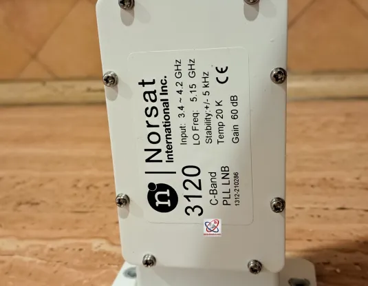
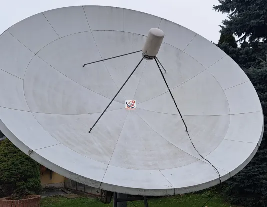
-Inštalovaný systém pre príjem v C pásme-
- Installed system for C-band reception-
-Installiertes System für den Empfang im C-Band-
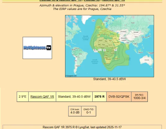
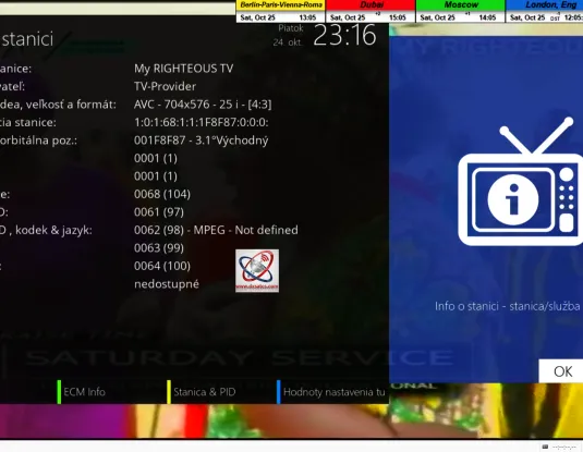
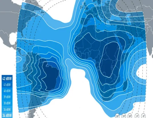
>SK_Aplikovaný priemer relektora typu Prodelin s priemerom D=450 cm pri satelitnom príjme v C pásme v mieste príjmu mesta Lučenec,vyžarovací diagram družice Rascom QAF-1R n 2,9°E v C pásme a analyzovaná nosná My Rightenous TV na nosnej frekvencii f=3 975 MHz_R na ktorej som vykonával dokazovanie vysokej rozdielnosti výsledkov kvality príjmu medzi konvertormi-LNB na báze DRO vs. PLL v signálnom monitoringu...
ENG_The applied diameter of a Prodelin-type reflector with D = 450 cm for satellite reception in the C-band at the reception site in the city of Lučenec, the radiation pattern of the Rascom QAF-1R satellite at 2.9°E in the C-band, and the analyzed carrier My Righteous TV at the carrier frequency f = 3,975 MHz_R, on which I conducted verification of the significant differences in reception quality results between DRO-based versus PLL-based LNB converters during signal monitoring...
DE_Der eingesetzte Durchmesser eines Prodelin-Reflektors mit D = 450 cm beim Satellitenempfang im C-Band am Empfangsort Stadt Lučenec, das Strahlungsdiagramm des Satelliten Rascom QAF-1R bei 2,9°E im C-Band und der analysierte Träger My Righteous TV auf der Trägerfrequenz f = 3.975 MHz_R, bei dem ich die hohen Unterschiede in der Empfangsqualität zwischen DRO-basierten und PLL-basierten LNB-Konvertern im Signalmonitoring überprüfte...
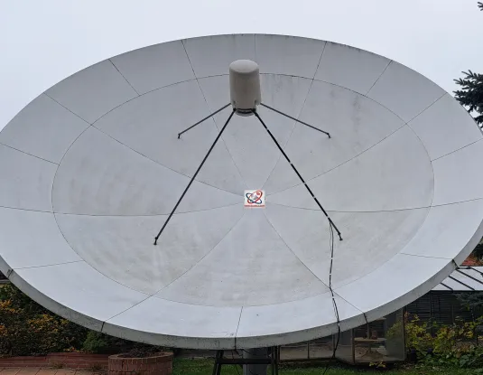
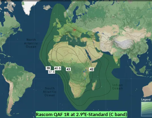
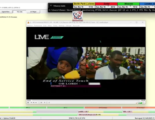
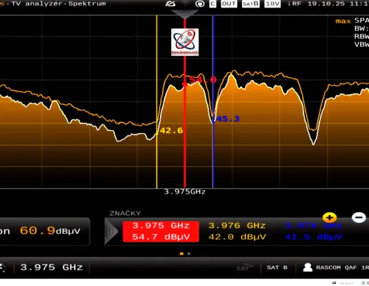
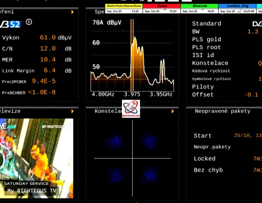
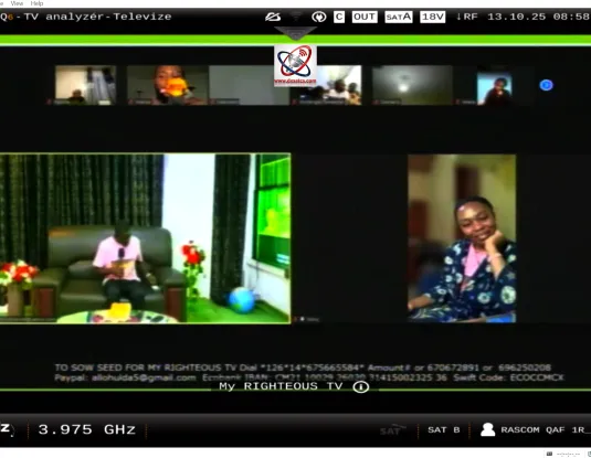
SK_Teraz Vám na nosnej s najnižšou aplikovanou hodnotou SR=1000 kSym/s a na nosnej s parametrom jedna s najnižších šíriek pásma nosnej CW=1,198 MHz na družici Rascom QAF-1R na 2,9°E nespochybnitelne dokážem neporovnatelne rozdielny priebeh signálneho monitoringu,stability a kvality príjmu medzi LNB na báze DRO a PLL.
ENG_Now, on the carrier with the lowest applied symbol rate SR = 1000 kSym/s and on the carrier with one of the lowest carrier bandwidth parameters CW = 1.198 MHz on the Rascom QAF-1R satellite at 2.9°E, I can indisputably demonstrate the incomparably different behavior of signal monitoring, stability, and reception quality between DRO-based and PLL-based LNBs.
DE_Nun kann ich auf dem Träger mit der niedrigsten angewendeten Symbolrate SR = 1000 kSym/s und auf dem Träger mit einem der niedrigsten Trägerbandbreitenparameter CW = 1,198 MHz auf dem Satelliten Rascom QAF-1R bei 2,9°E unbestreitbar das unvergleichlich unterschiedliche Verhalten der Signalüberwachung, Stabilität und Empfangsqualität zwischen DRO-basierten und PLL-basierten LNBs nachweisen.
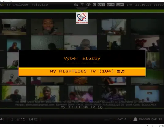
PF 450cm / My Rightenous TV _ f=3 975 MHz_R : DRO LNB Norsat 8215
Dokázatelne nestabilný príjem na 99,9% s trvalými výpadkami v Locku vplyvom vysokého LOF driftu na DRO LNB značky Norsat 8215.
Demonstrably unstable reception at 99.9% with persistent Lock outages due to high LOF drift on the DRO-based Norsat 8215 LNB.
Nachweislich instabiler Empfang zu 99,9 % mit anhaltenden Lock-Ausfällen aufgrund hoher LOF-Drifts am DRO-basierten Norsat 8215 LNB.
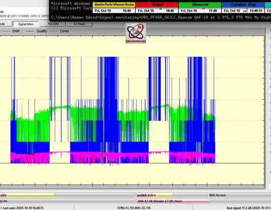
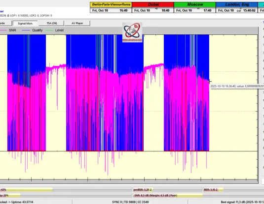
DRO-LNB-3975-R-My Righteous TV-totally-unstable-reception-with-permanent-outages-in-Lock
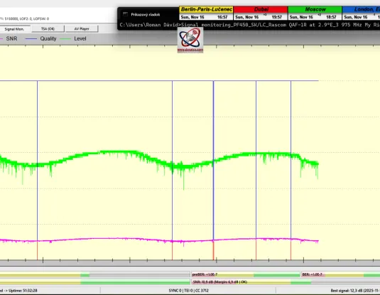
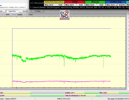
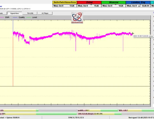
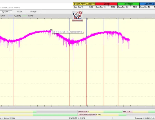
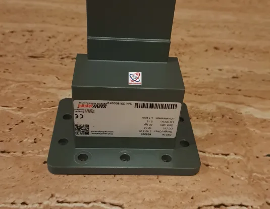
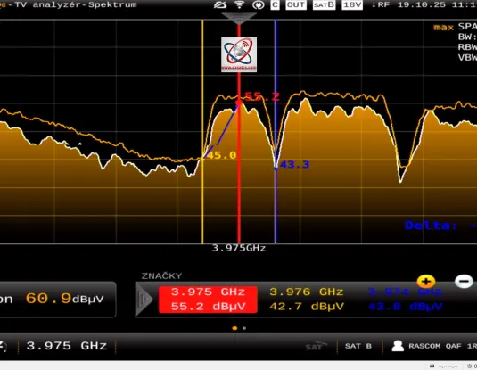
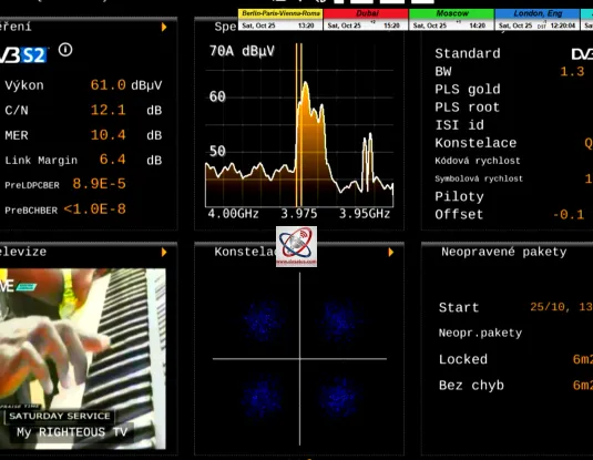
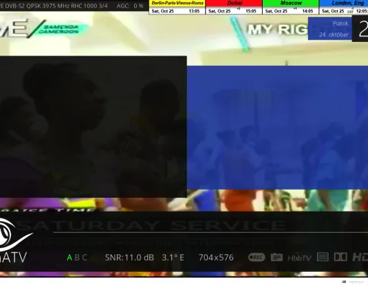
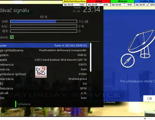
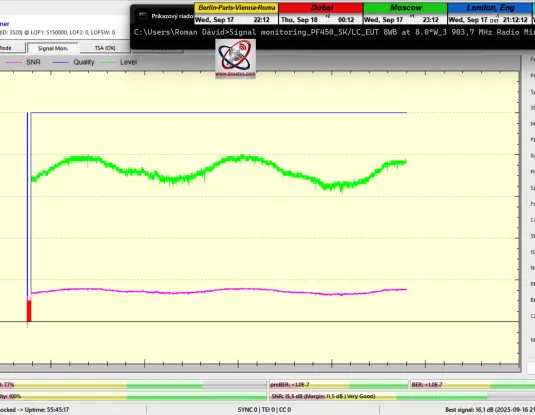
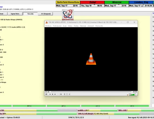
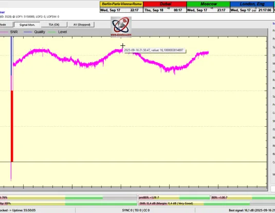
PF 450cm / My Rightenous TV _ f=3 975 MHz_R_SR-1000 kSym/s : PLL LNB Norsat 3120
SK_Dokázatelne stabilný príjem na 99-100% bez akýchkoľvek trvalých výpadkov v Locku z dôvodu vysokej LOF stability oscilátora +/- 5 kHz
ENG_Demonstrably stable reception at 99–100% without any persistent Lock outages due to the high LOF oscillator stability of ±5 kHz.
DE_Nachweislich stabiler Empfang zu 99–100 % ohne jegliche anhaltenden Lock-Ausfälle aufgrund der hohen LOF-Oszillatorstabilität von ±5 kHz.
TBS SNR peak quality : 12,3 dB ....Locked UPtime:51 hours ... (14-16.11.2025-last weekend)
SK_Stabilitu prímu na 99,66% som dosiahol aj napriek tomu že približne polovicu z celkovej jednotky signálneho monitoringu t=51 hodín prevládalo daždivé počasie v mieste príjmu Lučenec s nízkym úhrnom zrážok.
ENG_I achieved a reception stability of 99.66% despite the fact that approximately half of the total signal monitoring period of t = 51 hours was characterized by rainy weather at the reception site in Lučenec, with a low total rainfall.
DE_Ich erreichte eine Empfangsstabilität von 99,66 %, obwohl während etwa der Hälfte der gesamten Signalmonitoringdauer von t = 51 Stunden am Empfangsort in Lučenec regnerisches Wetter mit geringer Gesamtniederschlagsmenge vorherrschte.
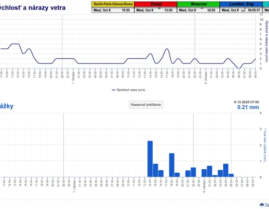
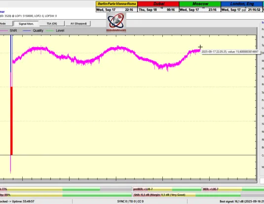
TBS SNR peak quality : 11,6 dB ....Locked UPtime:50 hours ... (6-8.10.2025)
SK_Stabilitu prímu na 100% bez jedinej pixelácie a bez jediného výpadku v kontinuite Locku som dosiahol aj napriek relatívne vysokém úhrnu dažďových zrážok v mieste príjmu v danom časovom rámci výkonu signálneho monitoringu.Dažďové prehánky boli hlavným faktorom,ktorý degradoval celkovú špičku kvality.
ENG_I achieved 100% reception stability without a single pixelation and without a single discontinuity in Lock, even despite a relatively high total rainfall at the reception site during the given time frame of signal monitoring.Rain showers constituted the dominant factor contributing to the degradation of the overall peak quality.
DE_Ich erreichte eine Empfangsstabilität von 100 % ohne auch nur eine einzige Pixelbildung und ohne jegliche Lock-Unterbrechung, und zwar trotz eines relativ hohen Gesamtniederschlags am Empfangsort während des entsprechenden Zeitraums des Signalmonitorings.Regenschauer waren der primäre Faktor, der die gesamte Spitzenqualität degradierte.
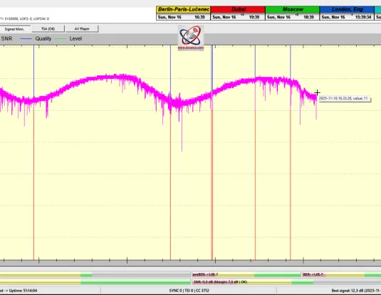
Demonstrably stable reception at 99–100% without any persistent Lock outages due to the high LOF oscillator stability of ±5 kHz.
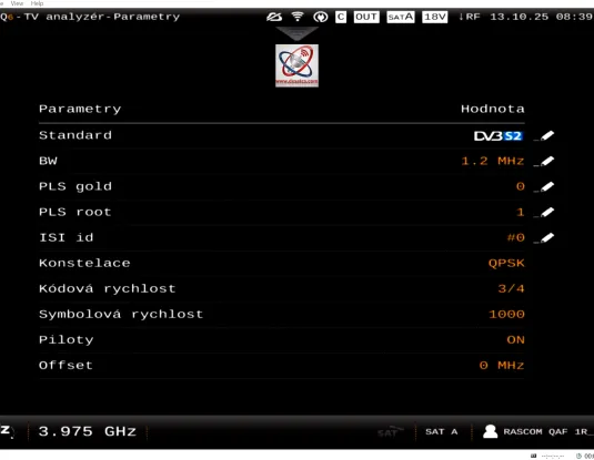
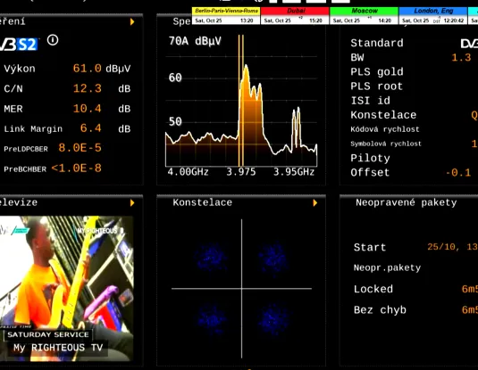
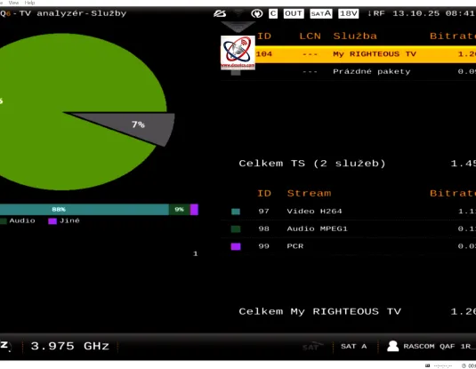
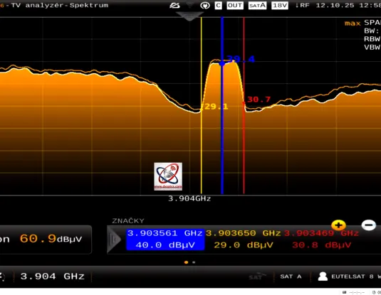
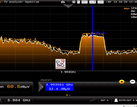
Televes Mosaiq-6 : 3 975 MHz-My Righteous TV_CW=1,198 MHz_SR=1000 kSym/s
SK_Analýza frekvenčného spektra,kvality,transportného streamu na jedinom analyzátore z testovaných,ktorý dokázal stabilne zamknúť danú nosnú prenosu na f=3 975 MHz s parametrom šírky pásma nosnej CW=1,198 MHz
ENG_Analysis of the frequency spectrum, quality, and transport stream on the only analyzer among those tested that was able to stably lock the given carrier transmission at f = 3,975 MHz with a carrier bandwidth parameter CW = 1.198 MHz.
DE_Analyse des Frequenzspektrums, der Qualität und des Transportstreams auf dem einzigen der getesteten Analysatoren, der in der Lage war, die gegebene Trägerübertragung bei f = 3,975 MHz mit einem Trägerbandbreitenparameter CW = 1,198 MHz stabil zu sperren.
dxsatcs.com-roman-dávid-rascom-qaf-1r-2.9e-c-band-reception-low-sr-case-study-televes-mosaiq-analysis-07
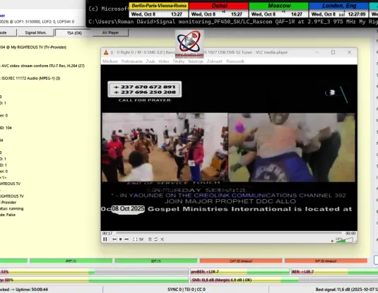
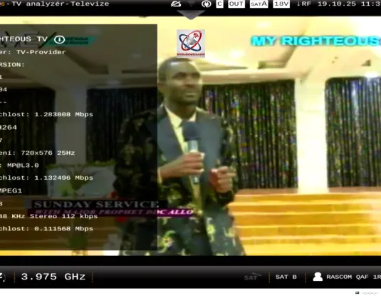
Octagon SF-4008 4K : 3 975 MHz-My Righteous TV_CW=1,198 MHz_SR=1000 kSym/s
SK_Normálna a denne sa opakujúca špička kvality viac ako SNR=11 dB na f=3 975 MHz na výstupe z Octagon SF 4008.Platí že 4K receiver Octagon zobrazuje kvalitu príjmu viac ako SNR=11 dB vtedy ked tunery TBS zobrazujú kvalitu oscilujúcu medzi SNR=12-12,5 dB,pri danej konfigurácii modulačných parametrov.
ENG_A normal and daily recurring quality peak of more than SNR=11 dB at f=3975 MHz at the output of the Octagon SF 4008. It holds that the 4K receiver Octagon displays a reception quality of more than SNR=11 dB when TBS tuners show a quality oscillating between SNR=12-12.5 dB, given the specific configuration of modulation parameters.
DE_Ein normaler und täglich wiederkehrender Qualitätsspitzenwert von mehr als SNR=11 dB bei f=3975 MHz am Ausgang des Octagon SF 4000. Es gilt, dass der 4K-Receiver Octagon eine Empfangsqualität von mehr als SNR=11 dB anzeigt, wenn TBS-Tuner bei der gegebenen Konfiguration der Modulationsparameter eine Qualität zwischen SNR=12-12,5 dB anzeigen.
dxsatcs.com-roman-dávid-rascom-qaf-1r-2.9e-c-band-reception-low-sr-case-study-octagon-sf4008-4k-gallery
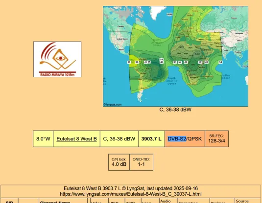
Eutelsat 8 West B at 8.0°W, 3903.7 MHz : Rádio Miraya , SR-128 kSym/s
>jedna z najnižších zdokumentovaných hodnôt symbolovej rýchlosti SR = 128 kSym/s aplikovaná v C pásme. Dokázatelne stabilný príjem na 100% so špičkou kvality SNR=16,1 dB (pri dosiahnutej okamžitej signálnej rezerve viac ako 12 dB_SNR) stanice Rádio Miraya (Eutelsat 8 West B, 8.0°W, 3903.7 MHz) je jasným dôkazom nielen extrémne vysokej kvality PLL oscilátora ale aj toho že som v praxi dokázal navrhnúť a realizovať profesionálny a plne funkčný signálny reťazec pre príjem tých najnižších SR v C pásme.
SK_Moje merania po výmene LNB potvrdili, že príjem v C-pásme sa stabilizoval nielen pre SR v rozsahu 1000–2000 kSym/s na Rascom QAF-1R, ale dokonca aj pre najnižšiu dokumentovanú hodnotu SR = 128 kSym/s v tomto pásme. Dokázatelne stabilný príjem na 100% so špičkou kvality SNR=16,1 dB (pri dosiahnutej okamžitej signálnej rezerve viac ako 12 dB_SNR) stanice Rádio Miraya (Eutelsat 8 West B, 8.0°W, 3903.7 MHz) je jasným dôkazom nielen extrémne vysokej kvality PLL oscilátora ale aj toho že som v praxi dokázal navrhnúť a realizovať profesionálny a plne funkčný signálny reťazec pre príjem tých najnižších SR v C pásme.
ENG_My measurements after the LNB replacement confirmed that C-band reception stabilized not only for SR in the range of 1000–2000 kSym/s on Rascom QAF-1R, but even for the lowest documented SR value of 128 kSym/s in this band. The demonstrably stable reception at 100% with a quality peak of SNR=16.1 dB (with an achieved instantaneous signal reserve of more than 12 dB_SNR) for the Radio Miraya station (Eutelsat 8 West B, 8.0°W, 3903.7 MHz) is clear evidence not only of the extremely high quality of the PLL oscillator but also that I have practically demonstrated the ability to design and implement a professional and fully functional signal chain for receiving the lowest SR values in the C-band.
DE_Meine Messungen nach dem LNB-Wechsel bestätigten, dass der C-Band-Empfang nicht nur für SR im Bereich von 1000–2000 kSym/s auf Rascom QAF-1R stabilisiert wurde, sondern sogar für den niedrigsten dokumentierten SR-Wert von 128 kSym/s in diesem Band. Der nachweislich stabile Empfang zu 100% mit einer Qualitätsspitze von SNR=16,1 dB (bei einer erreichten momentanen Signalreserve von mehr als 12 dB_SNR) des Senders Radio Miraya (Eutelsat 8 West B, 8.0°W, 3903.7 MHz) ist ein klarer Beweis nicht nur für die extrem hohe Qualität des PLL-Oszillators, sondern auch dafür, dass ich in der Praxis in der Lage war, eine professionelle und voll funktionsfähige Signalkette für den Empfang der niedrigsten SR-Werte im C-Band zu entwerfen und zu realisieren.
PLL-lowest-SR-C band-dxsatcs.com-roman-dávid-eutelsat-8-west-b-c-band-reception-3 903.7 Radio Miraya-033
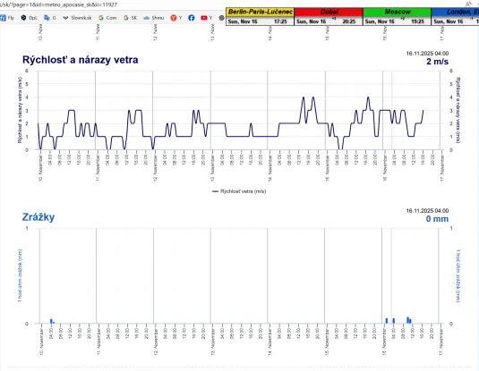
Eutelsat 8 West B-8.0°W,3903.7 MHz : Rádio Miraya,
SR=128 kSym/s,SNRpeak=16,1 dB , t=55 h.
SK_Toto je Jedna z najnižších zdokumentovaných hodnôt symbolovej rýchlosti SR = 128 kSym/s v C pásme. Dokázatelne stabilný príjem na 100% so špičkou kvality SNR=16,1 dB (pri dosiahnutej okamžitej signálnej rezerve viac ako 12 dB_SNR) stanice Rádio Miraya (Eutelsat 8 West B, 8.0°W, 3903.7 MHz)v jednotke signálneho monitoringu t=55 hodín, je jasným dôkazom nielen extrémne vysokej kvality PLL oscilátora ale aj toho že som v praxi dokázal navrhnúť a realizovať profesionálny a plne funkčný signálny reťazec pre príjem tých najnižších SR v C pásme.
ENG_This is one of the lowest documented symbol rate values, SR = 128 kSym/s, applied in the C-band. The demonstrably stable reception at 100% with a quality peak of SNR=16.1 dB (with an achieved instantaneous signal reserve of more than 12 dB_SNR) for the Radio Miraya station (Eutelsat 8 West B, 8.0°W, 3903.7 MHz) is clear evidence not only of the extremely high quality of the PLL oscillator but also that I have practically demonstrated the ability to design and implement a professional and fully functional signal chain for receiving the lowest SR values in the C-band.
DE_Dies ist einer der niedrigsten dokumentierten Symbolratenwerte, SR = 128 kSym/s, der im C-Band angewendet wird. Der nachweislich stabile Empfang zu 100% mit einer Qualitätsspitze von SNR=16,1 dB (bei einer erreichten momentanen Signalreserve von mehr als 12 dB_SNR) des Senders Radio Miraya (Eutelsat 8 West B, 8.0°W, 3903.7 MHz) ist ein klarer Beweis nicht nur für die extrem hohe Qualität des PLL-Oszillators, sondern auch dafür, dass ich in der Praxis in der Lage war, eine professionelle und voll funktionsfähige Signalkette für den Empfang der niedrigsten SR-Werte im C-Band zu entwerfen und zu realisieren.
PLL-lowest-SR-C band-dxsatcs.com-roman-dávid-eutelsat-8-west-b-c-band-reception-3 903.7 Radio Miraya-TBS-signal-monitoring-55h-tbs-5927
PLL LNB
PLL LNB
PLL LNB
PLL LNB-Televes-Mosaiq-6
PLL LNB-Televes-Mosaiq-6
PLL LNB-Televes-Mosaiq-6
PLL LNB
PLL LNB
DRO LNB
DRO LNB
Autor prípadovej štúdie : Roman Dávid/Lučenec-vedec a vynálezca v oblasti vlnovej fyziky a satelitného príjmu z domény www.dxsatcs.com